This post provides a quick tutorial that demonstrates the basic steps of connecting via a Virtual Private Network (VPN) a VMware as a Service – single tenant instance with a Juniper vSRX. The vSRX can either be deployed in IBM Cloud Classic Infrastructure or in a client datacenter. The steps that follow will create a basic working environment, providing a VPN and basic firewall implementation, with test virtual machines that can be used to verify that the end-to-end environment is functional.
This post is broken into three steps to make implementation easier. These steps are:
- Requirements gathering
- vSRX configuration
- VMware as a Service – single tenant configuration
This guide should take around thirty minutes to complete and assumes that VMware as a Service – single tenant, the vSRX, as well as any test networks have already been provisioned.
Requirements gathering
Before attempting to go through this tutorial it will be useful to have the following information available.
- Network behind the vSRX
- In the examples that follow 10.176.68.64/26 is used. This is the subnet that will be shared from the client or IBM Cloud Classic Infrastructure network.
- Network behind the VMware as a Service – single tenant edge gateway
- In the examples that following 192.168.100.0/24 is used. This is the subnet that will be shared from the VMware as a Service – single tenant instance.
- Public IP address of the vSRX
- In the examples 169.46.39.226 is used.
- Public IP address of the VMware as a Service – single tenant edge gateway
- In the examples 150.240.144.2 is used.
The following assumptions are also made:
- No Network Address Translation (NAT) is being used
- You have administrative access to all components
- No conflicting IPv4 ranges
vSRX Configuration
When the Juniper VPN receives a connection request establish a connection, Juniper uses IPsec Phase 1 parameters to establish a secure connection and authenticate the VMware as a Service – single tenant connection. Then, if the security policy permits the connection, the Juniper VPN establishes the tunnel using IPsec Phase 2 parameters and applies the IPsec security policy. Key management, authentication, and security services are negotiated dynamically through the IKE protocol.
To support these functions, you must do the following on the Juniper vSRX unit:
- Define the Phase 1 parameters that the Juniper vSRX VPN requires to authenticate the remote peer and establish a secure connection.
- Define the Phase 2 parameters that the Juniper vSRX VPN requires to create a VPN tunnel with VMware as a Service – single tenant.
General configuration steps are as follows.
- Choose IKEv2 in Phase 1.
- Set up policy-based mode.
- Enable DH-group 19 in the Phase 1 proposal.
- Set lifetime = 36000 in the Phase 1 proposal.
- Enable PFS in the Phase 2 proposal.
- Set lifetime = 10800 in the Phase 2 proposal.
- Input your peer and subnet information in the Phase 2 proposal.
- Allow UDP 500 traffic on the external interface.
The first step is to log into your vSRX and configure the necessary settings. To do so enter configuration mode and enter the following commands.
Configure an IKE proposal for a policy-based VPN.
set security ike proposal ike-phase1-vmaas authentication-method pre-shared-keys
set security ike proposal ike-phase1-vmaas dh-group group14
set security ike proposal ike-phase1-vmaas authentication-algorithm sha-256
set security ike proposal ike-phase1-vmaas encryption-algorithm aes-256-cbc
set security ike proposal ike-phase1-vmaas lifetime-seconds 28800

set security ike policy ike-phase1-policy mode main
set security ike policy ike-phase1-policy proposals ike-phase1-vmaas
set security ike policy ike-phase1-policy pre-shared-key ascii-text <your-psk>
Configure an IKE gateway to a policy-based VPN gateway.
set security ike gateway vmaas ike-policy ike-phase1-policy
set security ike gateway vmaas address 150.240.144.2
set security ike gateway vmaas external-interface ae1.0
set security ike gateway vmaas version v2-only
Configure an IPsec proposal for a policy-based VPN.
set security ipsec proposal ipsec-phase2-vmaas protocol esp
set security ipsec proposal ipsec-phase2-vmaas authentication-algorithm hmac-sha-256-128
set security ipsec proposal ipsec-phase2-vmaas encryption-algorithm aes-256-cbc
set security ipsec proposal ipsec-phase2-vmaas lifetime-seconds 3600

set security ipsec policy ipsec-phase2-policy perfect-forward-secrecy keys group14
set security ipsec policy ipsec-phase2-policy proposals ipsec-phase2-vmaas
Configure a VTI and VPN connection to a policy-based VPN gateway.
set interfaces st0 unit 0 family inet
set security ipsec vpn VMASSVPN bind-interface st0.0
set security ipsec vpn VMASSVPN ike gateway vmaas
set security ipsec vpn VMASSVPN ike ipsec-policy ipsec-phase2-policy
set security ipsec vpn VMASSVPN traffic-selector pair1 local-ip 10.176.68.64/26
set security ipsec vpn VMASSVPN traffic-selector pair1 remote-ip 192.168.100.0/24
set security ipsec vpn VMASSVPN establish-tunnels immediately
Configure a control plane firewall to permit IKE/IPsec protocol traffic.
set firewall filter PROTECT-IN term IPSec-IKE from source-address 150.240.144.2/32
set firewall filter PROTECT-IN term IPSec-IKE from protocol udp
set firewall filter PROTECT-IN term IPSec-IKE from port 500
set firewall filter PROTECT-IN term IPSec-IKE then accept

set firewall filter PROTECT-IN term IPSec-ESP from source-address 150.240.144.2/32
set firewall filter PROTECT-IN term IPSec-ESP from protocol esp
set firewall filter PROTECT-IN term IPSec-ESP then accept

set firewall filter PROTECT-IN term IPSec-4500 from source-address 150.240.144.2/32
set firewall filter PROTECT-IN term IPSec-4500 from protocol udp
set firewall filter PROTECT-IN term IPSec-4500 from port 4500
set firewall filter PROTECT-IN term IPSec-4500 then accept
Configure a data plane firewall to allow traffic between on-premises and IBM VMware as a Service – Single Tenant.
set security zones security-zone vpn-vmaas interfaces st0.0
set security policies from-zone vsrx-vlan to-zone vpn-vmaas policy vlan_to_vmaas match source-address any
set security policies from-zone vsrx-vlan to-zone vpn-vmaas policy vlan_to_vmaas match destination-address any
set security policies from-zone vsrx-vlan to-zone vpn-vmaas policy vlan_to_vmaas match application any
set security policies from-zone vsrx-vlan to-zone vpn-vmaas policy vlan_to_vmaas then permit

set security policies from-zone vpn-vmaas to-zone vsrx-vlan policy vmass_to_vlan match source-address any
set security policies from-zone vpn-vmaas to-zone vsrx-vlan policy vmass_to_vlan match destination-address any
set security policies from-zone vpn-vmaas to-zone vsrx-vlan policy vmass_to_vlan match application any
set security policies from-zone vpn-vmaas to-zone vsrx-vlan policy vmass_to_vlan then permit
Configure TCP MSS clamping on vSRX to avoid unnecessary fragmentation.
set security flow tcp-mss ipsec-vpn mss 1360After the configuration commits, you can check the connection status from the CLI using the following command:
run show security ipsec security-associations
VMware as a Service – Single Tenant Configuration
The next step is to log into your VMware as a Service – single tenant instance and deploy the initial network that will be used for testing.
To log in and deploy the initial network:
- From the instance log in page, log in using admin as the user ID and the password as provided in the IBM Cloud portal.
- In the top menu navigation click on Networking.
- Click on Edge Gateways Name of your Edge Gateway –> IP Sets
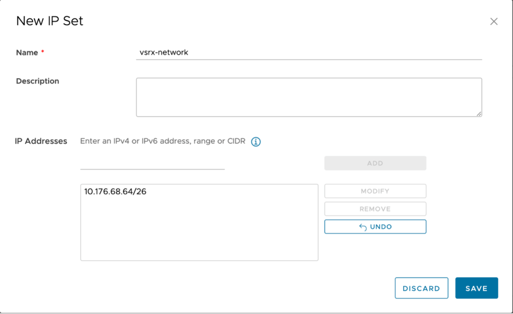
- Click on new to create a new IP Set:
- Name: vsrx-network
- IP Address: CIDR block of your network behind the vSRX (10.176.68.64/26 in the example).
- Create a second IP set for your network behind the Edge Gateway in VMware as a Service – single tenant. In the example vmass-network is used as the name and 192.168.100.0/24 (same as the network created in step one) is used. Click add to add the IP set then click Save to complete the window. The new IP set will be added.
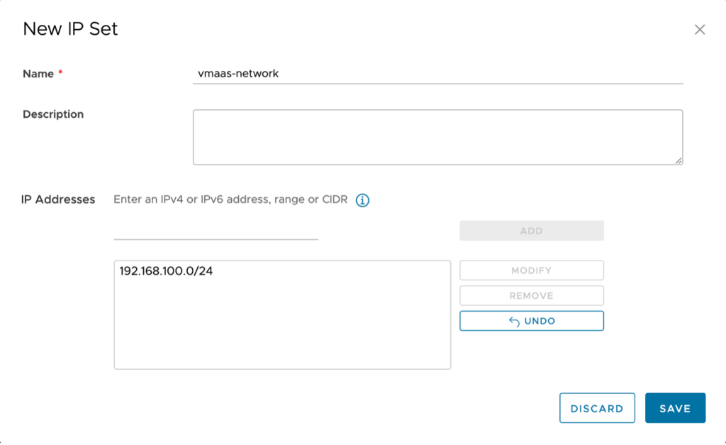
Stay on this screen and proceed to the next step.
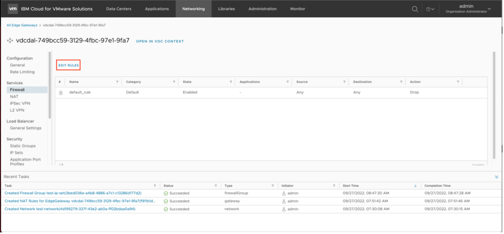
- Create a firewall rule.
The next step is to create a firewall rule. By default, the VMware as a Service – single tenant instance has been provisioned with a default firewall rule that will drop all traffic to ensure security. Two additional rules must be put in place to allow the traffic to and from the VPN connection.
To create a firewall rule:
- From the previous step, click on Firewall.

- Click on Edit Rules.
- Click on New on Top to create a new firewall rule above the default drop all rule.

- A new entry in the firewall rule list will be created. This entry needs to be completed. To complete the entry:
- Name – VMaaS-to-vSRX
- Source – click on the pencil icon next to source and select the vmaas-network created in the previous step. Click on Keep when complete.
- Destination – click on the pencil icon next to destination and select the vsrx-network created in the previous step.
Review the inputs and click on Save when complete. The new firewall rule will be created.
- Repeat the previous step, except this time you will reverse the source and destination networks. To complete the entry:
- Name – vSRX-to-VMaaS
- Source – click on the pencil icon next to source and select the vsrx-network created in the previous step. Click on Keep when complete.
- Destination – click on the pencil icon next to destination and select the vmaas-network created in the previous step.
Review the inputs and click on Save when complete. The new firewall rule will be created.
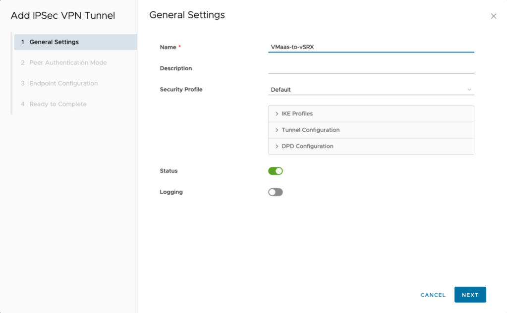
- The next step is to create the IPSec VPN. Switch to IPSec VPN in the left navigate then click on New to start the wizard.
- Name – VmaaS-to-vSRX
- Next (NOTE: after creation the security profile will be adjusted)
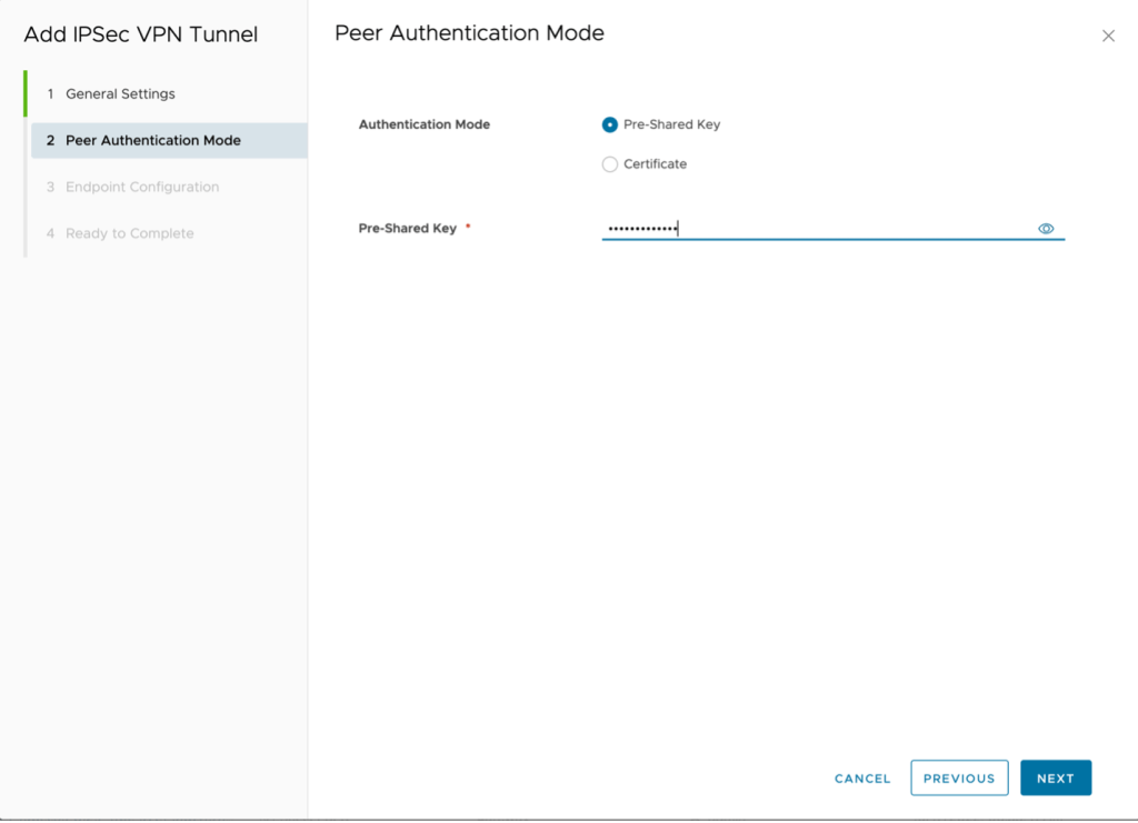
- PSK
- Type the same key as before and click Next.
Local endpoint IP address – 150.240.144.2
Networks – 192.168.100.0/24 (subnet in VMware as a Service – single tenant)
Remote endpoint IP address – 169.46.39.226
Networks – 10.176.68.64/26
Remote ID – Leave blank (defaults to remote IP address)

Click on Next to Continue.
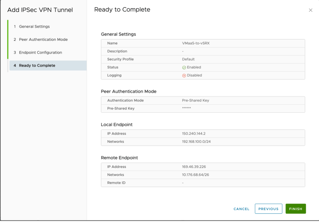
Click Finish.
Click on the tunnel and select Security Profile Customization

Adjust the following values for both the IKE profiles and the tunnel configuration.:
Encryption: AES256
Digest: SHA 2 – 256
Diffie-Hellman Group: 14
Key Life Time: 28800
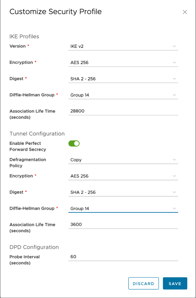
Click Save to complete the configuration.
At this point if all steps have been completed successfully your VPN tunnel will be established and traffic will flow between the two networks.


Leave a comment