Last week I covered setting up a VPN between IBM Cloud VMware as a Service and a Juniper vSRX.
The purpose of this guide is to provide a quick guided tutorial that can be used to demonstrate the basic initial steps of connecting via a Virtual Private Network (VPN) a VMware as a Service – single tenant instance with a FortiGate appliance. This FortiGate appliance can either be deployed in IBM Cloud Classic Infrastructure or in a client datacenter. The steps that follow will create a basic working environment providing a VPN and basic firewall implementation, with test virtual machines that demonstrate that the end-to-end environment is functional.
This guide is broken into two steps to make implementation easier. These steps are:
- Requirements gathering
- FortiGate configuration
- VMware as a Service – single tenant configuration
This guide should take around thirty minutes to complete and assumes that VMware as a Service – single tenant, the FortiGate, as well as any test networks have already been provisioned.
Requirements gathering
Before attempting to go through this tutorial it will be useful to have the following information available.
- Network behind the FortiGate
- In the examples that follow 10.184.149.0/26 is used. This is the subnet that will be shared from the client or IBM Cloud Classic Infrastructure network.
- Network behind the VMware as a Service – single tenant edge gateway
- In the examples that following 192.168.100.0/24 is used. This is the subnet that will be shared from the VMware as a Service – single tenant instance.
- Public IP address of the FortiGate
- In the examples 169.47.110.4 is used.
- Interface the public IP address of the FortiGate is assigned to
- In the example v800-f-outside is used.
- Public IP address of the VMware as a Service – single tenant edge gateway
- In the examples 150.240.132.162 is used.
The following assumptions are also made:
- No Network Address Translation (NAT) is being used
- You have administrative access to all components
- No conflicting IPv4 ranges
- FortiGate Configuration
The first step is to log into your FortiGate appliance and configure the necessary settings.
Once logged in:
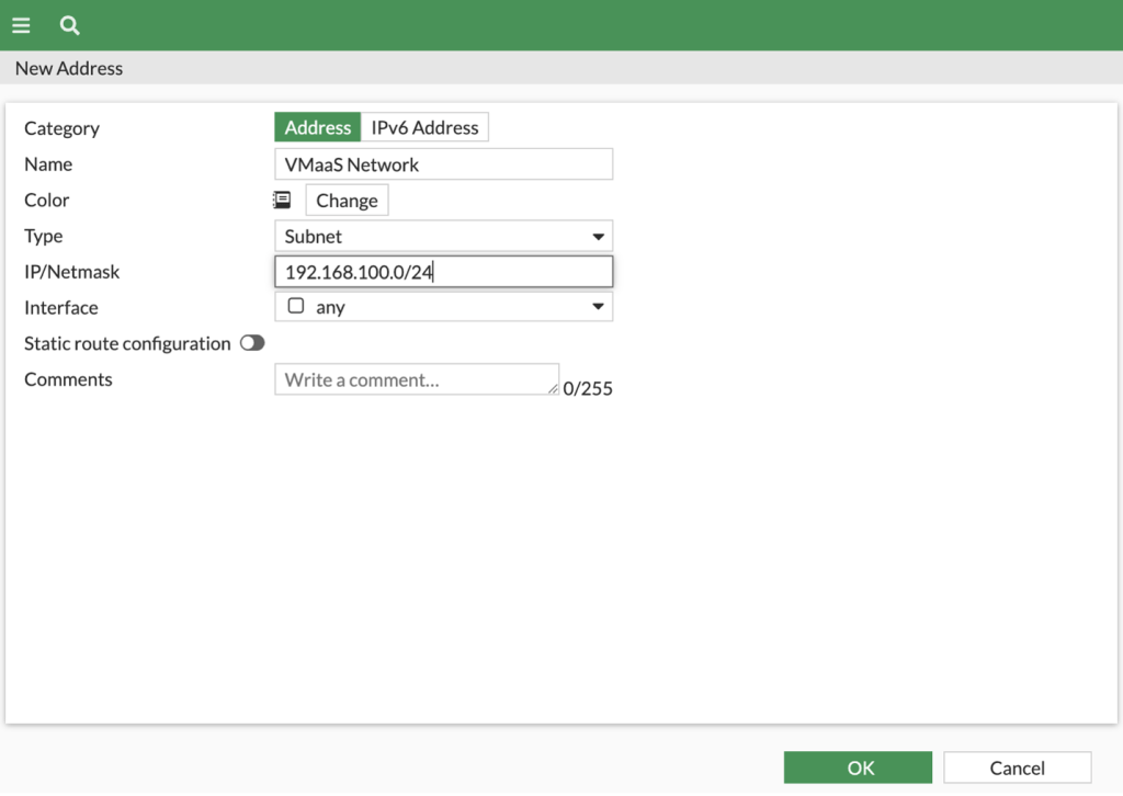
- Create a new address object (or objects & groups) under Policy & Objects -> Addresses for the client network behind the FortiGate.
- Name = VMaas Network (Name to your needs)
- Type = Subnet
- IP/Netmask = 192.168.100.0/24 (adjust as needed for your network)
- Interface = any
- Create a second address object under Policy & Objects -> Addresses for the server network behind the Edge Gateway.
- Name = FortiGateNetwork (Name to your needs)
- Type = Subnet
- IP/Netmask = 10.184.149.0/26 (adjust as needed for your network)
- Interface = any

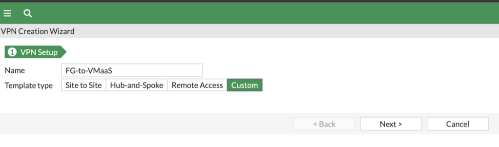
- Create the IPsec Tunnel under VPN -> IPsec Wizard.
- Name = Fg-to-VMaaS (Name to your needs)
- Template type = Custom
- Click Next to continue.
Network
- IP Address = 150.240.132.162 (Public IP address of your edge gateway in VMware as a Service)
- Interface = Interface the public IP address is assigned to – v800-f-outside is used in the example
- NAT Traversal = Disable

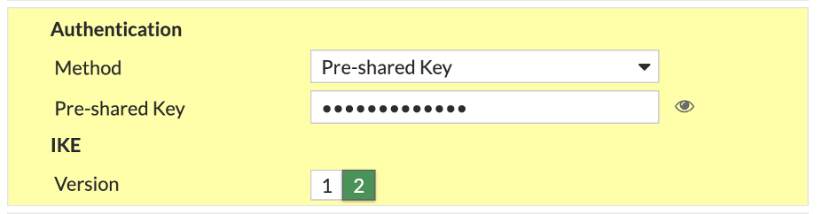
Authentication
- Method = Pre-shared Key
- Pre-shared Key = Enter your PSK (up to 128 char, no “)
- IKE Version = 2
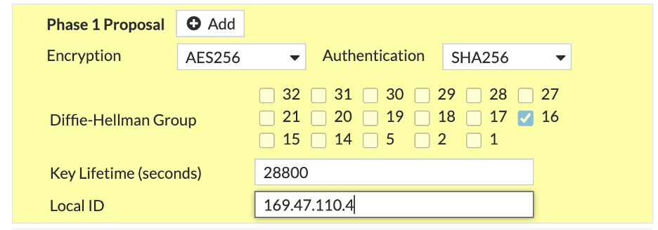
Phase 1 Proposal
- Remove all existing ciphers.
- Set Encryption to AES256
- Set Authentication to SHA256
- Diffie-Hellman Group set to 16, deselect all others
- Key Lifetime = 28800 (seconds)
- Local ID = 169.47.110.4 (public IP address of the FortiGate)
Phase 2 Selectors (New Phase 2)
- Local Address = Named Address = FortigateNetwork
- Remote Address = Named Address = VMaas Network
- Remove all existing ciphers.
- Set Encryption to AES256
- Set Authentication to SHA256
- Diffie-Hellman Group set to 16, deselect all others
- Key Lifetime = 3600 (seconds)
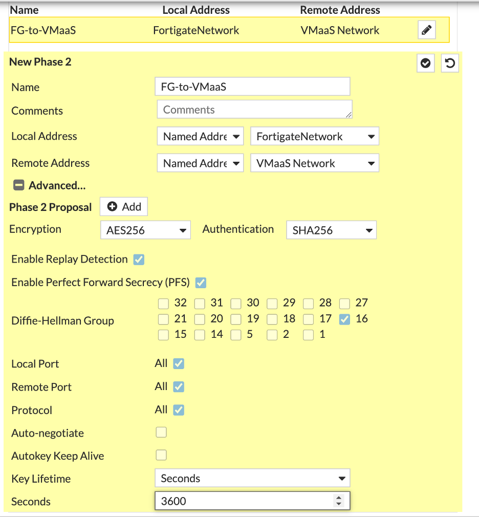
Click OK when complete.
- Create a new rule under Policy & Objects -> Firewall Policy so that the client traffic can be forwarded through the tunnel towards the destination. Obviously, make this as strict or as lenient as you need.
- Name = PermiFG-to-VMaas-Policy
- Incoming Interface = The interface your client virtual machines are connected to – v1281-b-inside in the example
- Outgoing Interface = VPN tunnel created in the previous step
- Source = FortiGateNetwork
- Destination = VMaaS Network
- Schedule = always
- Service = All
- Action = ACCEPT
- NAT = Disable
- Enable this policy = Enable

Click OK when complete.
- Add any other additional firewall rules that may be needed for your environment.
- Create a blackhole static route for the destination network. This is to prevent traffic from going down the wrong path in case the tunnel goes down, and would also prevent routing loops in a situation where the tunnel is down for whatever reason.
Under Network -> Static Routes -> Create New:
- Destination = CIDR block of the client virtual machines in VMware as a Service – single tenant (192.168.100.0/24 in the example)
- Interface = Blackhole
- Administrative Distance = 254
- Status = Enabled

- Create a static route for the destination network.
Under Network -> Static Routes -> Create New:
- Destination = CIDR block of the client virtual machines in VMware as a Service – single tenant (192.168.100.0/24 in the example)
- Interface = FG-to-VMaaS (VPN tunnel created previously)
- Administrative Distance = 10
- Status = Enabled

Click OK when complete.
- Open a CLI Console and run the commands listed below:
config vpn ipsec phase1-interface

edit FG-to-VMaaS
set localid-type address
end
When you type in the local ID for the Phase 1 tunnel, the FortiGate firewalls do their best to guess what you want, but in many cases, it decides to use the ID as a string and not as the raw IPv4 address. This doesn’t work with the vCloud Edge Gateway, which won’t accept the IP address as a string of characters. The change above must be done on the FortiGate and can’t be made from the WebUI, which is why we drop to a command shell.
VMware as a Service – Single Tenant Configuration
The second step is to log into your VMware as a Service – single tenant instance and deploy the initial network that will be used for testing.
To log in and deploy the initial network:
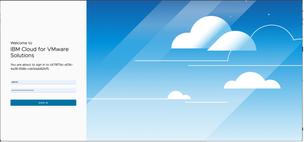
- From the instance log in page, log in using admin as the user ID and the password as provided in the IBM Cloud portal.
- In the top menu navigation click on Networking.
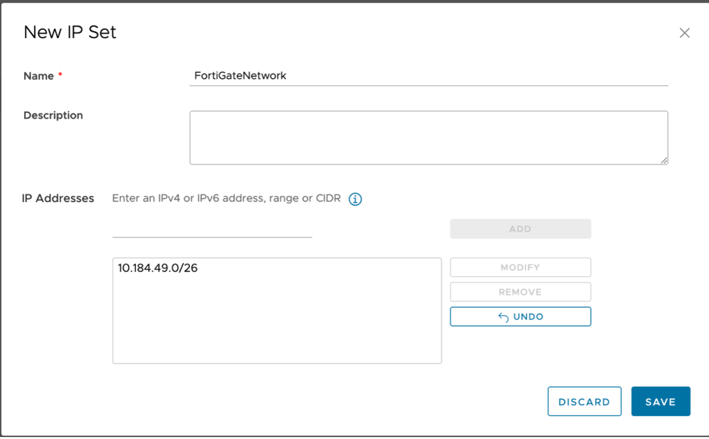
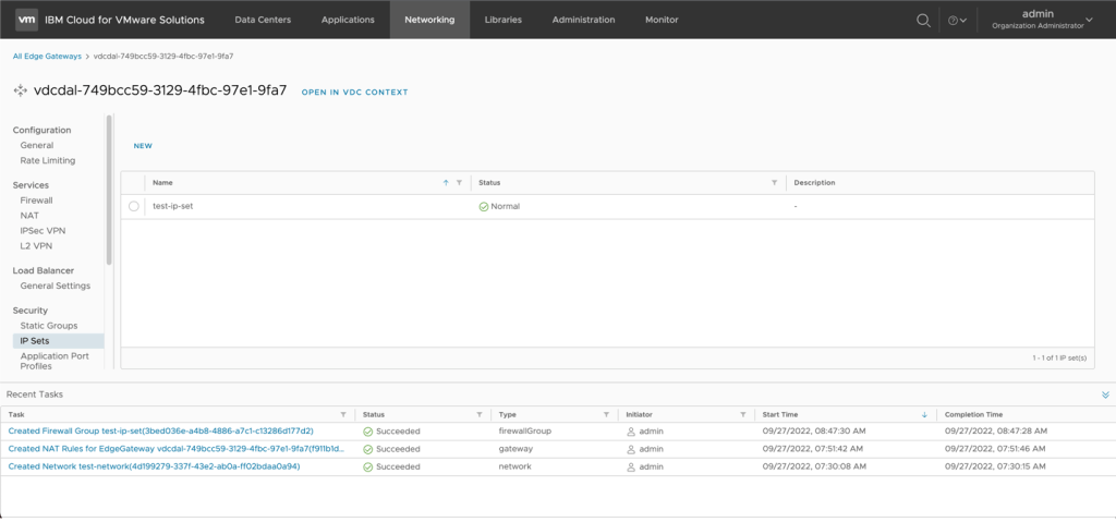
- Click on Edge Gateways Name of your Edge Gateway –> IP Sets
- Click on new to create a new IP Set:
- Name: FortiGateNetwork
- IP Address: CIDR block of your network behind the FortiGate.
- Create a second IP set for your network behind the Edge Gateway in VMware as a Service – single tenant. In the example test-ip-set is used as the name and 192.168.100.0/24 (same as the network created in step one) is used. Click add to add the IP set then click Save to complete the window. The new IP set will be added.
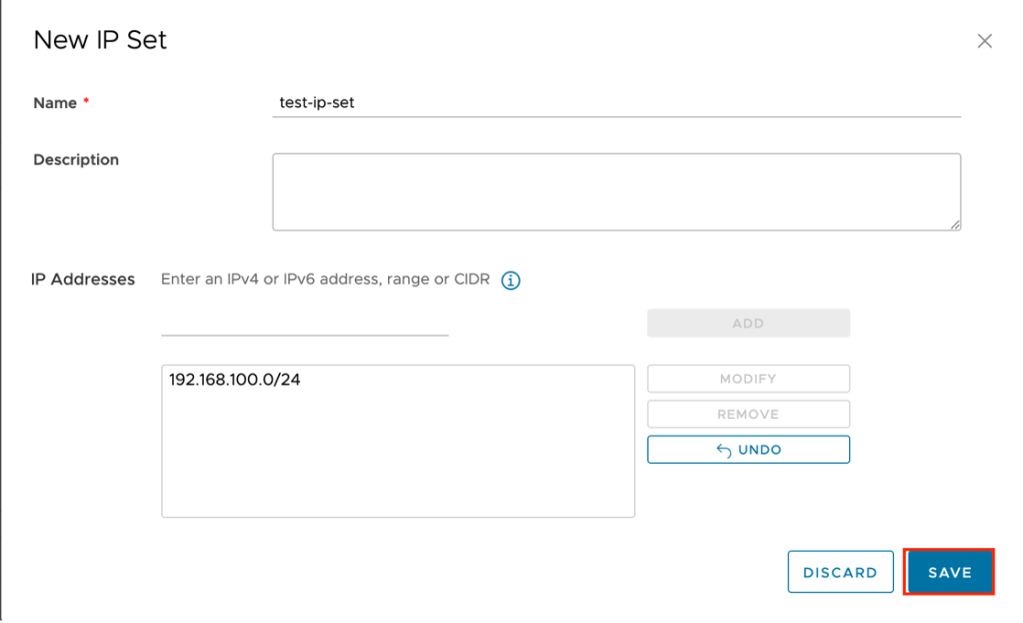
Stay on this screen and proceed to the next step.
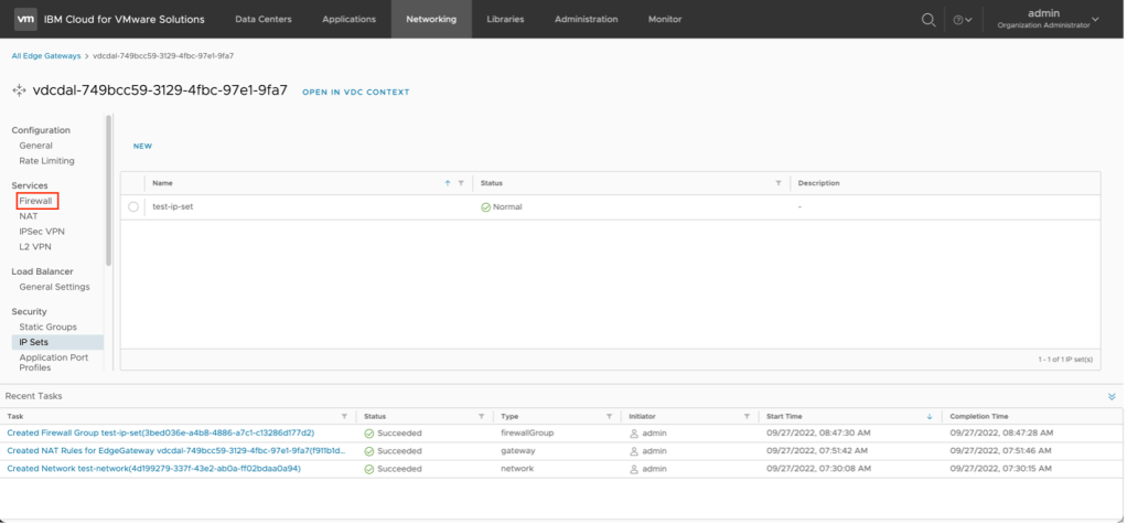
- Create a firewall rule.
The next step is to create a firewall rule. By default, the VMware as a Service – single tenant instance has been provisioned with a default firewall rule that will drop all traffic to ensure security. Two additional rules must be put in place to allow the traffic to and from the VPN connection.
To create a firewall rule:
- From the previous step, click on Firewall.
- Click on Edit Rules.
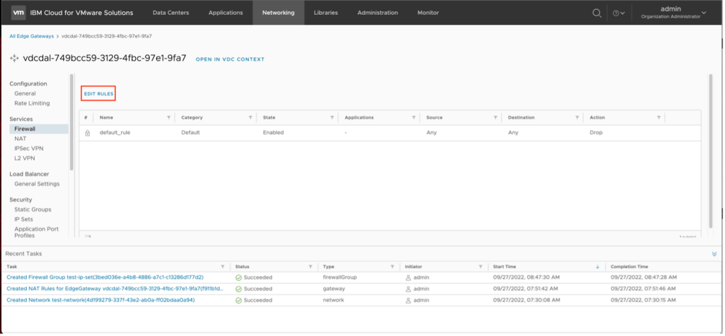
- Click on New on Top to create a new firewall rule above the default drop all rule.

- A new entry in the firewall rule list will be created. This entry needs to be completed. To complete the entry:
- Name – VMaaS-to-FG
- Source – click on the pencil icon next to source and select the test-ip-rule created in the previous step. Click on Keep when complete.
- Destination – click on the pencil icon next to destination and select the FortiGateNetwork created in the previous step.
Review the inputs and click on Save when complete. The new firewall rule will be created.
- Repeat the previous step, except this time you will reverse the source and destination networks. To complete the entry:
- Name – FG-to-VMaaS
- Source – click on the pencil icon next to source and select the FortiGateNetwork created in the previous step. Click on Keep when complete.
- Destination – click on the pencil icon next to destination and select the test-ip-set created in the previous step.
Review the inputs and click on Save when complete. The new firewall rule will be created.
- The next step is to create the IPSec VPN. Switch to IPSec VPN in the left navigate then click on New to start the wizard.
- Name – VmaaS-to-FG
- Next (NOTE: after creation the security profile will be adjusted)
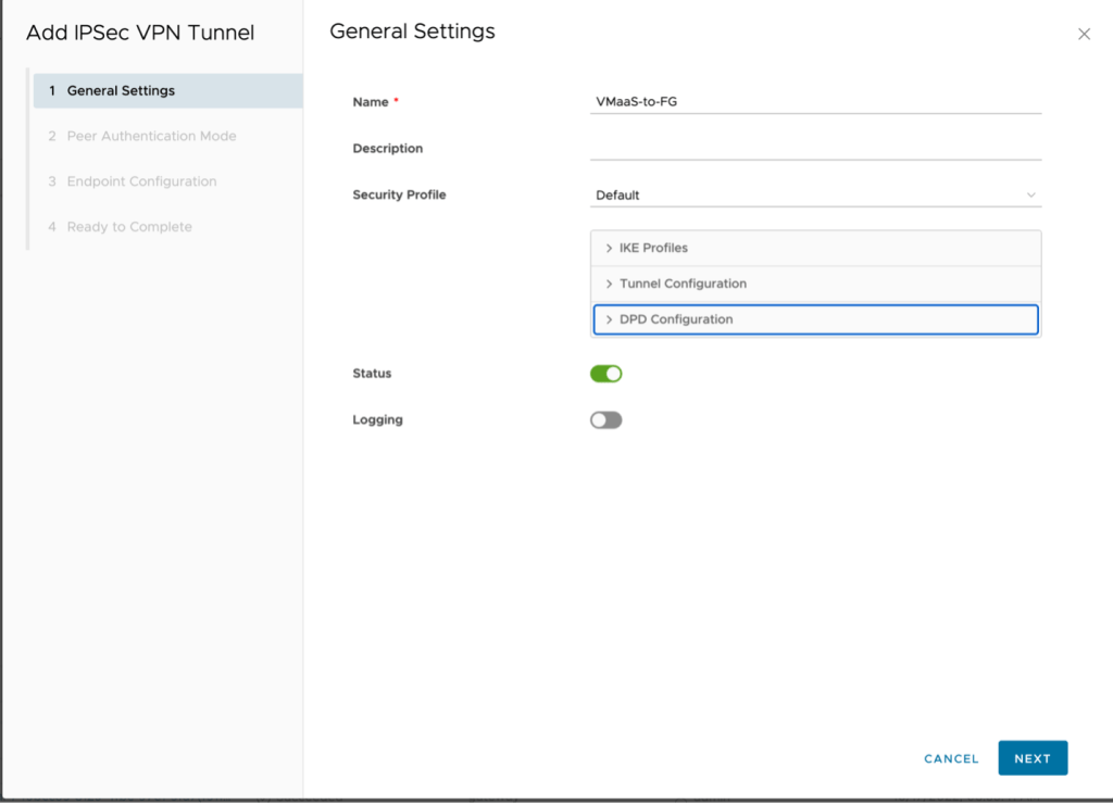
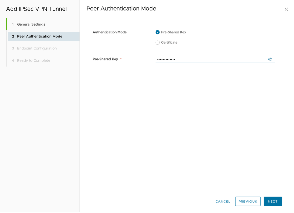
- PSK
- Type the same key as before and click Next.
- Local endpoint IP address – 150.240.132.162
- Networks – 192.168.100.0/24 (subnet in VMware as a Service – single tenant)
- Remote endpoint IP address – 169.47.110.4
- Networks – 10.194.149.0/26
- Remote ID – 169.47.100.4

Click on Next to Continue.
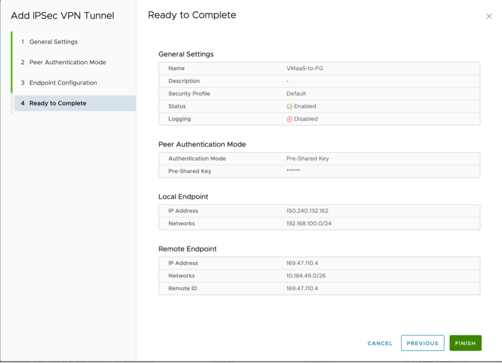
Click Finish.
Click on the tunnel and select Security Profile Customization

Adjust the following values for both the IKE profiles and the tunnel configuration.:
- Encryption: AES256
- Digest: SHA 2 – 256
- Diffie-Hellman Group: 16
- Key Life Time: 28800
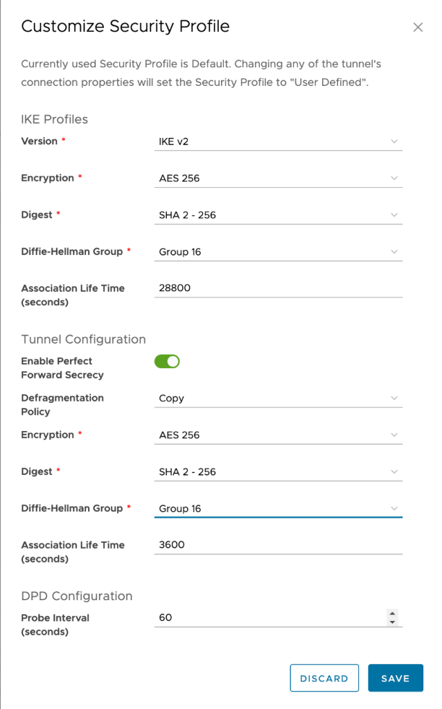
Click Save to complete the configuration.
At this point if all steps have been completed successfully your VPN tunnel will be established and traffic will flow between the two networks.


Leave a comment