While VMware Cloud Director is a powerful and easy way to provide a multi-tenant environment to clients for service providers, often client will want to bring their own networking and load balancing technologies to the environment. This is the philosophy of “use what you know” and I strongly recommend it, especially if you have already invested in licenses and skills for specific products.
This tutorial series will go through integrating the F5 BIG-IP load balancer into your VMware Cloud Director environment as a tenant. For this first part, I will cover the initial network deployment prior to installing the F5 appliance. Specifically, I will be using IBM Cloud VMware Solutions Shared, which is backed by NSX-V. A future blog post will cover integrating with a Cloud Director environment backed by NSX-T (now just NSX).
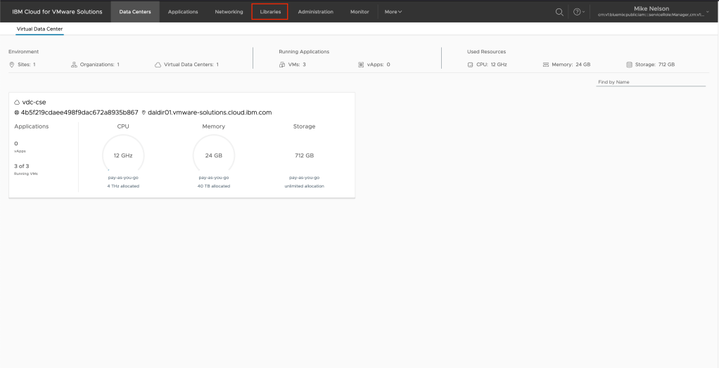
To begin, log into your VMware Cloud Director or IBM Cloud for VMware Solutions Shared environment using the URL provided by the provider. Since my environment is integrated with IBM Cloud IAM, I will be logging in via SSO. Otherwise log in with your user name and password.

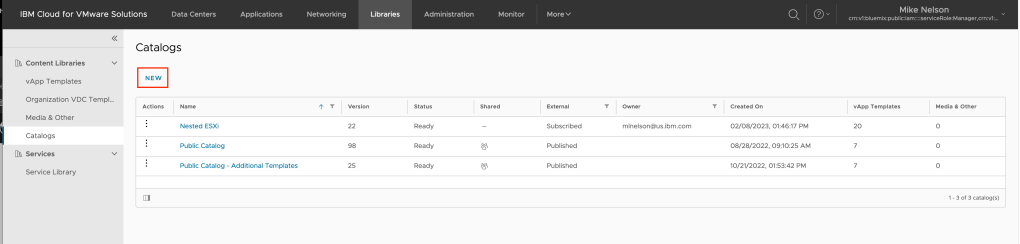
The first thing we want to do is create a catalog and upload our F5 OVA to that catalog. To do so, in the upper navigate click on Libraries.
In the left hand navigation, click on Catalogs.

Click on NEW to create a new catalog.
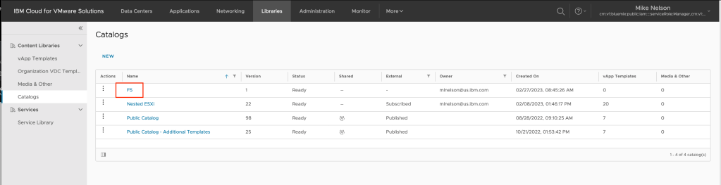
At a minimum, give you catalog a name then click OK. In my example I am calling my catalog F5 Images.

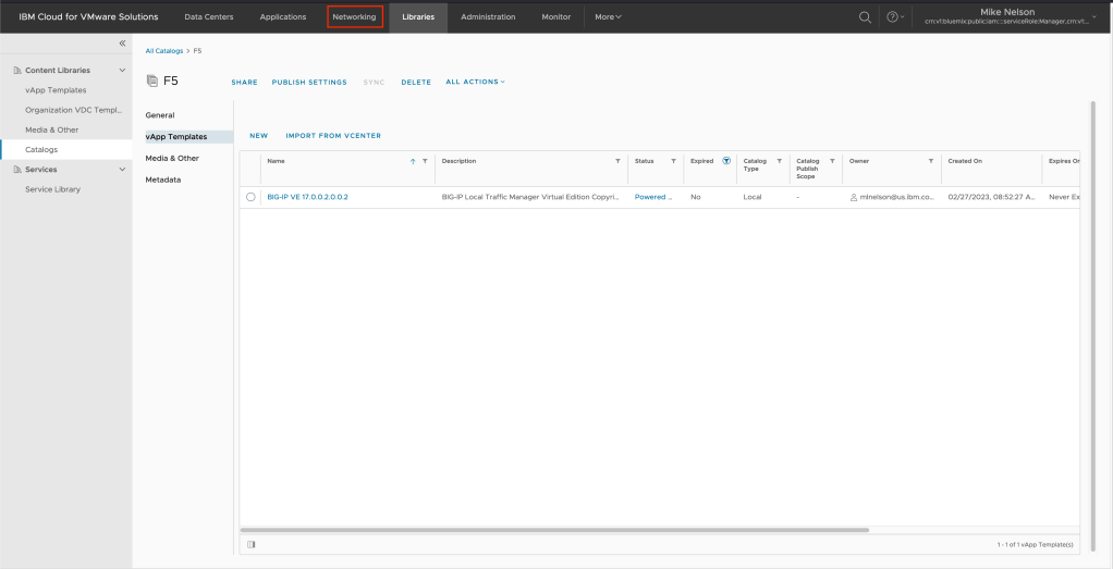
Once you catalog is created, click on the name of the catalog.
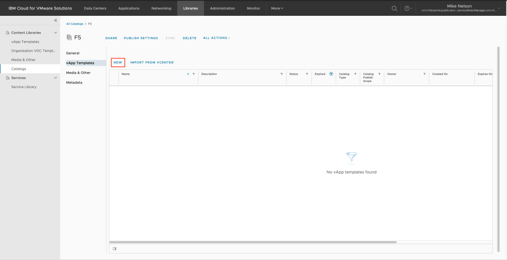
And click on NEW to create a new vApp Template.
Change the radio selection to Browse then using the navigation select the folder and F5 OVA image you have previously downloaded. Click on NEXT to continue.

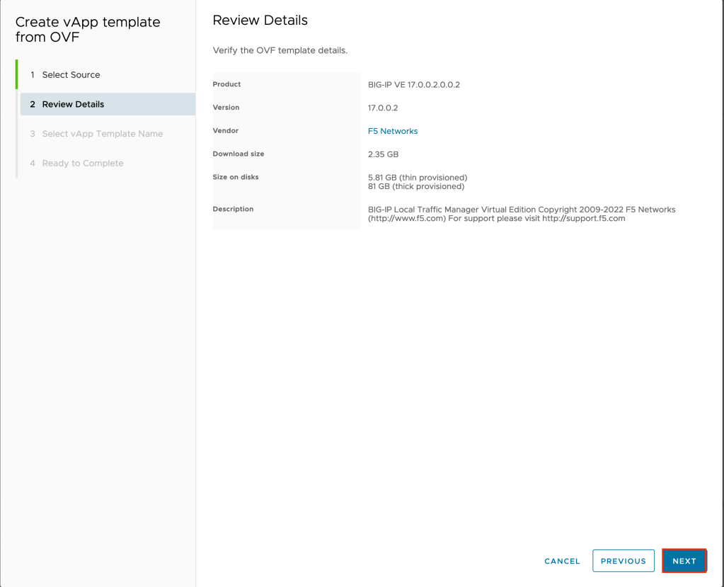
On the review details page click on NEXT to continue.
Change the default name if you wish, then click on NEXT to continue.

Click on FINISH to complete the wizard and begin uploading the F5 OVA to the catalog.

Depending on your upload speed, this may take some time.
Either while your OVA is uploading or when complete, we need to create a few networking objects that will comprise our management network. These are:
- Routed network for F5 management
- NAT rules to both allow the F5 to access the Internet during configuration, and to allow for access to the Web UI. This is required to activate the F5 licensing. Alternatively you can activate licensing manually but that will not be covered in this tutorial.
- Appropriate firewall rules to allow through the management network.
First, let’s create our routed network. Click on Networking in the upper navigation.
Click on NEW to create a new network.

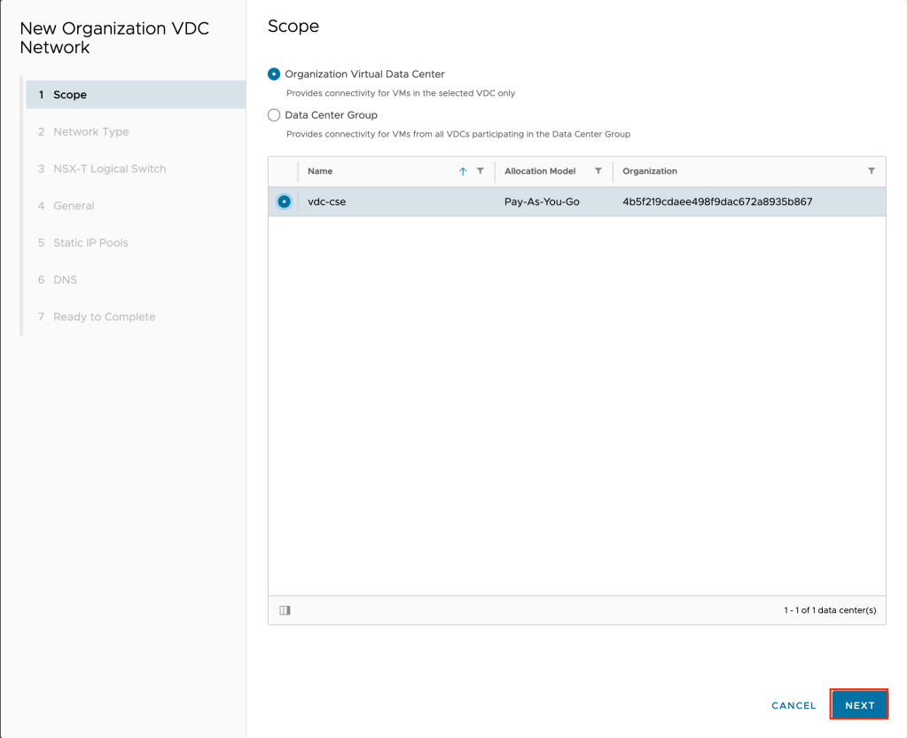
On the scope page of the wizard, click on the virtual data center you wish to create the network in and click NEXT.
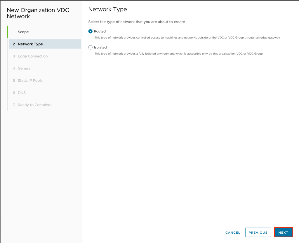
On the network type page leave the default of routed and click NEXT.
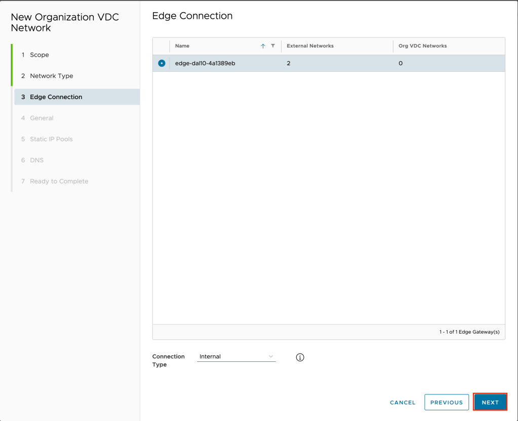
Select the edge you wish to create the network on and leave the connection type as internal and click NEXT.
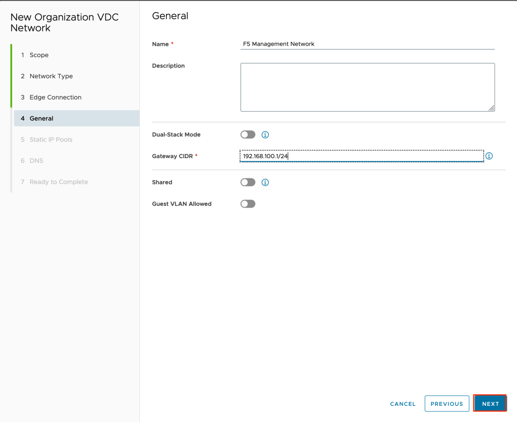
Give the network a name and a gateway CIDR. In the example for the CIDR 192.168.100.1/24 is used. For production I would recommend a much smaller range.
On the static IP pools page, type in the pool to use and click on NEXT to continue. While we will be manually assigning the IP address of the F5 management interface we still need to assign a pool. In the example 192.168.100.100-192.168.100.200 is used.

Since we will need DNS to activate the F5 virtual machine, choose a DNS server that is resolvable for your environment. First, deselect the option to use Edge DNS. As this tutorial uses IBM Cloud for VMware Solutions Shared, the IBM Cloud external DNS servers of 161.26.0.10 and 161.26.0.11 are used. Click NEXT to continue.

Review your inputs and click on FINISH to complete the wizard and create the new network.

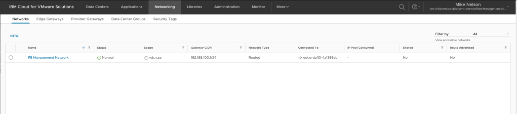
It may take a few minutes for your network to be created. When complete the status will change to Normal in the UI.
The next step is creating network address translation (NAT) rules to both allow our F5 virtual machine to access the Internet (for registration) as well as to access the web UI directly.
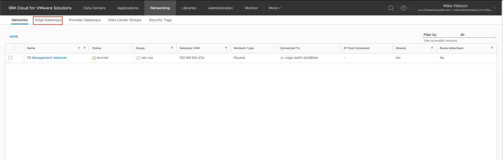
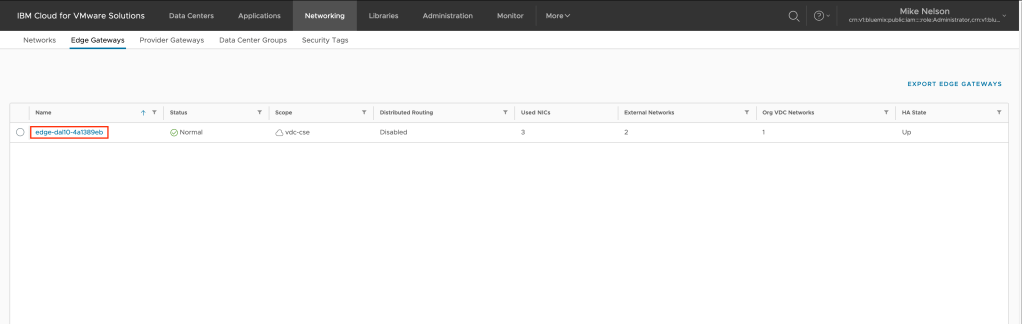
From the previous step, click on Edge Gateways.
Click on the edge gateway you wish to create the NAT rules upon.
In the middle navigation, click on Services.
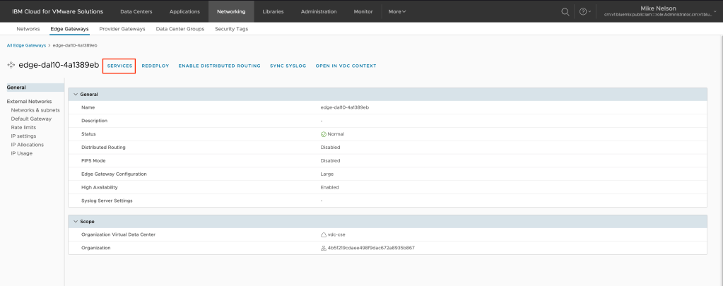
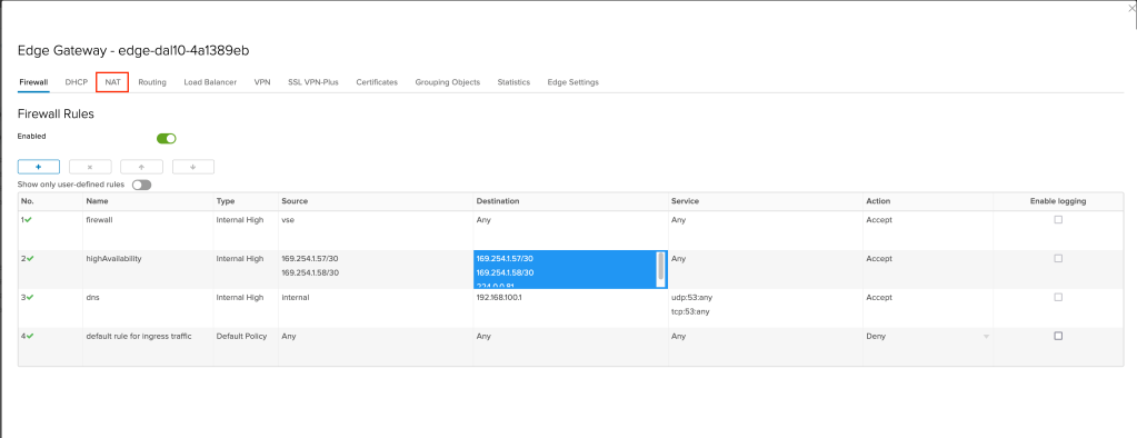
Click on NAT.
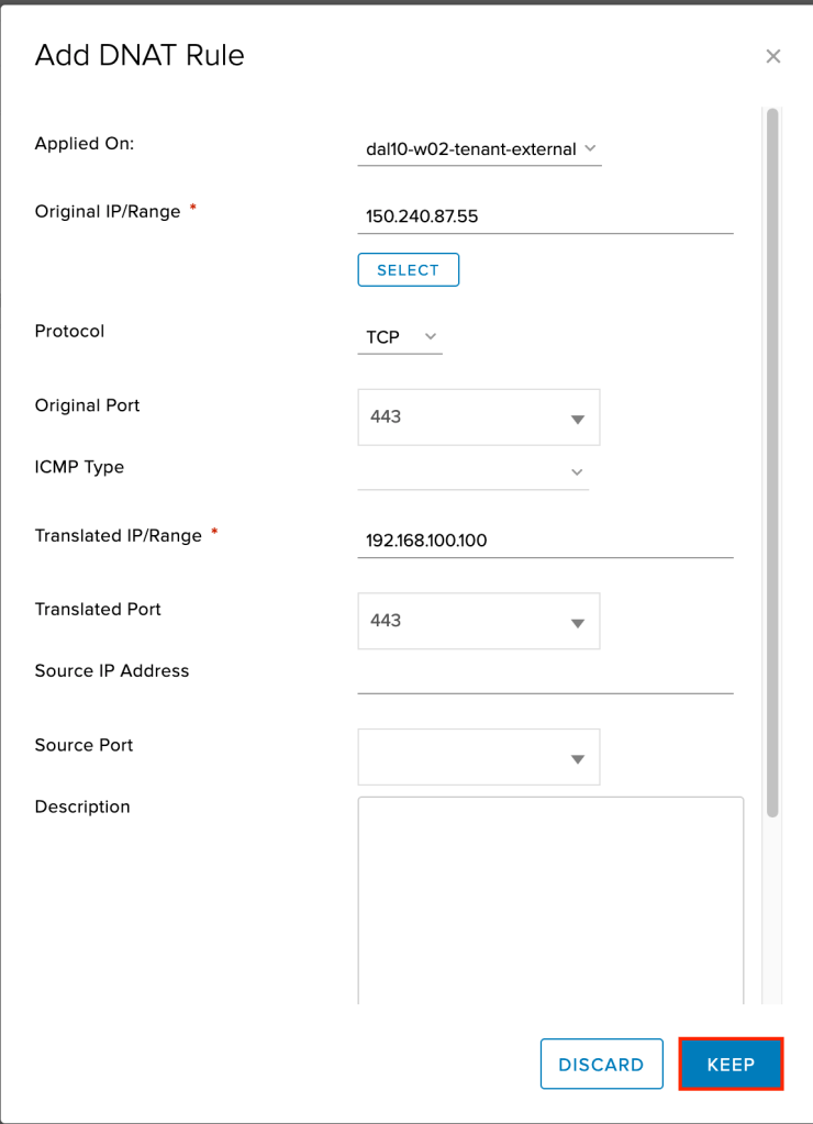
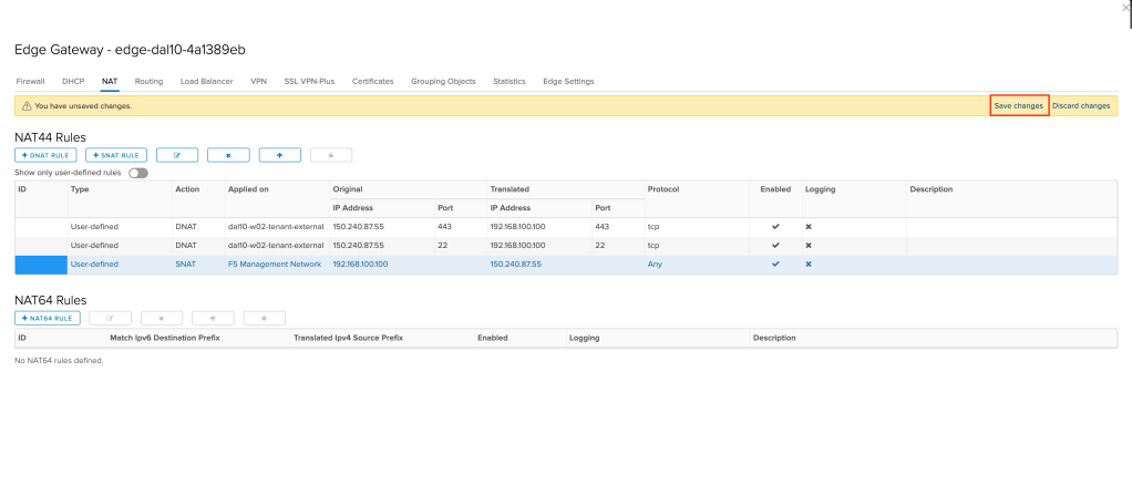
We need to create two DNAT (destination NAT) rules and a SNAT (source NAT) rule as we will be allowing access in both directions. First, we will create the DNAT rules. Before doing so, based upon the CIDR block you created earlier select an IP address that will be used for the management interface of your F5. In the following examples 192.168.100.100 will be used.
Click on +DNAT RULE to create a new rule.
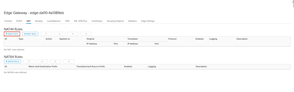
A new window will appear. We want to fill in the following values:
- Applied on: Select your external network. This was likely provisioned for you by your provider. In the example
dal10-w02-tenant-externalis used. - Original IP/Range: Using the select button select an external IP address. In the example
150.240.87.55is used. - Protocol: Select TCP
- Original Port: In the box type 443 (for HTTPS).
- Translated IP/Range: Type in the IP address that will be used for the management interface of your F5. In the example
192.168.100.100is used. - Translated Port: In the box type 443 (for HTTPS).
Leave all other values at their default and click KEEP to create the new DNAT rule.
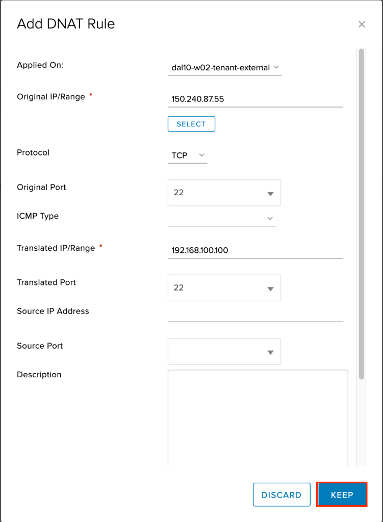
Repeat the same steps as above, except this time for the original and translated port use port 22 (SSH). This is to allow SSH into the F5 once it is deployed.
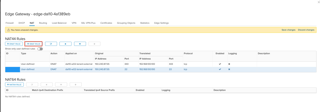
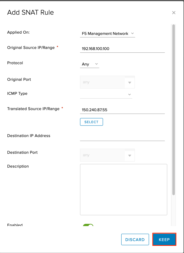
Next we need to create a SNAT rule, allowing the F5 virtual machine to access the Internet. To do so, click on +SNAT RULE.
A new window will appear. We want to fill in the following values:
- Applied on: Select your F5 management network. In the example
F5 Management Networkis used. - Original IP/Range: Type in the IP address that will be used for the management interface of your F5. In the example
192.168.100.100is used. - Protocol: Leave as
Any(default). - Translated IP/Range: Select the same IP address you used in your DNAT rules for the external network. In the example
150.240.87.55is used.
Leave all other values at their default and click KEEP to create the new SNAT rule.
Finally, we need to save the three new NAT rules we created. Click on Save changes to save and activate your new rules.
Finally, to complete this part of the tutorial we need to create firewalls rule allowing both our F5 virtual machine out to the Internet as well as inbound from the Internet. To start, click on Firewall in the gateway navigation.

Click on the + symbol to add a new rule.
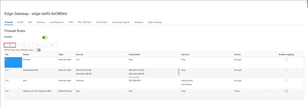
A new rule row will appear. For the values:
- Name: Give the rule a name. In the example
F5 Outbound Management Ruleis used. - Source: Use the IP address of the F5 management interface. In the example
192.168.100.100is used.
Leave all other values at default. Click on the + symbol again to create a second rule.
Again, a new rule row will appear. For the values:
- Name: Give the rule a name. In the example F5 Inbound Management Rule is used.
- Destination: Use the IP address of the F5 management interface. In the example
150.240.87.55is used.
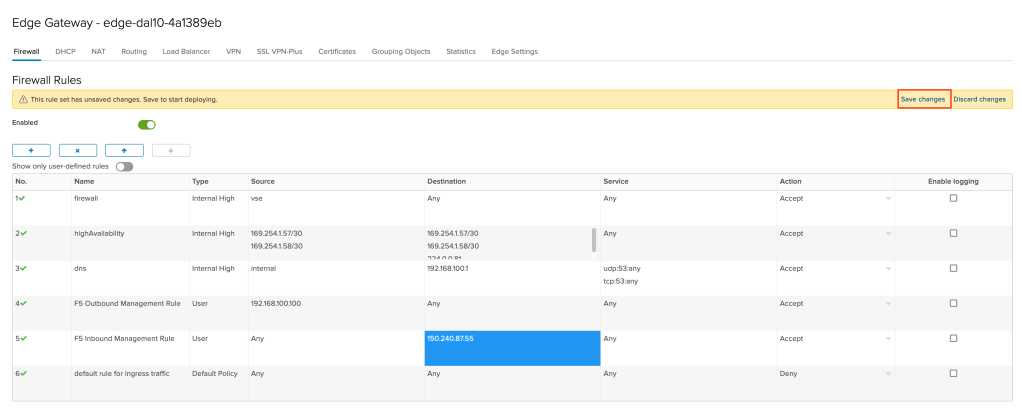
Leave all other values at default. Click on Save changes to complete your firewall rules and deploy them to the environment.
This concludes part one of this tutorial. In part two I will cover deploying the F5 and configuring the management interface.


Leave a comment