In part one of this series, I covered the initial network deployment prior to installing the F5 appliance. Part two covered the actual installation of the F5. Part three covered initial configuration and activation of the F5 appliance.
In this fourth part, I will cover setting up the internal and external networks for the appliance in VMware Cloud Director.
To start this part, log into your Cloud Director virtual data center and navigate to the networking tab. So far – we have only created a single network which was used for F5 management.
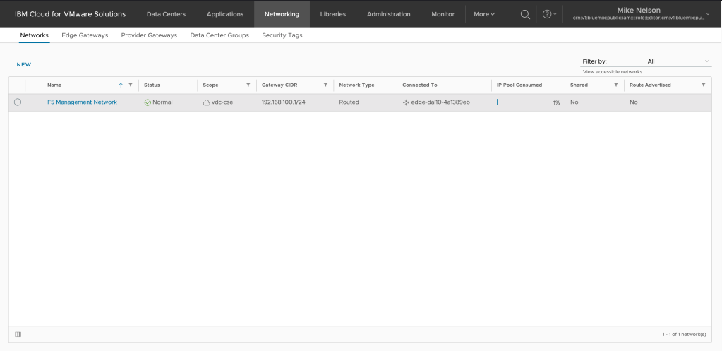
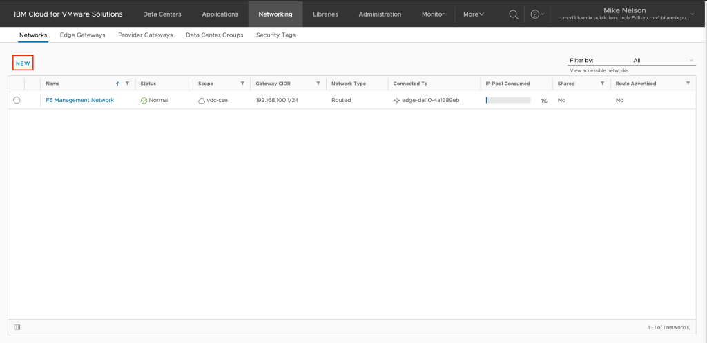
We are going to create two new networks – one for the inside interface of the F5 and one for the outside interface. To begin, click on NEW to create a new network.
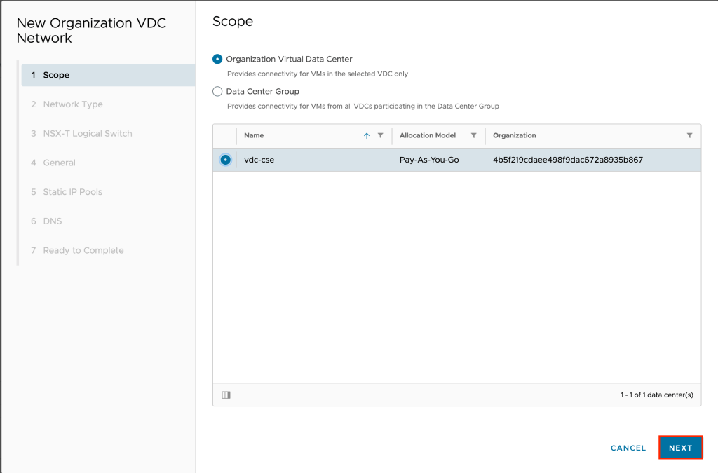
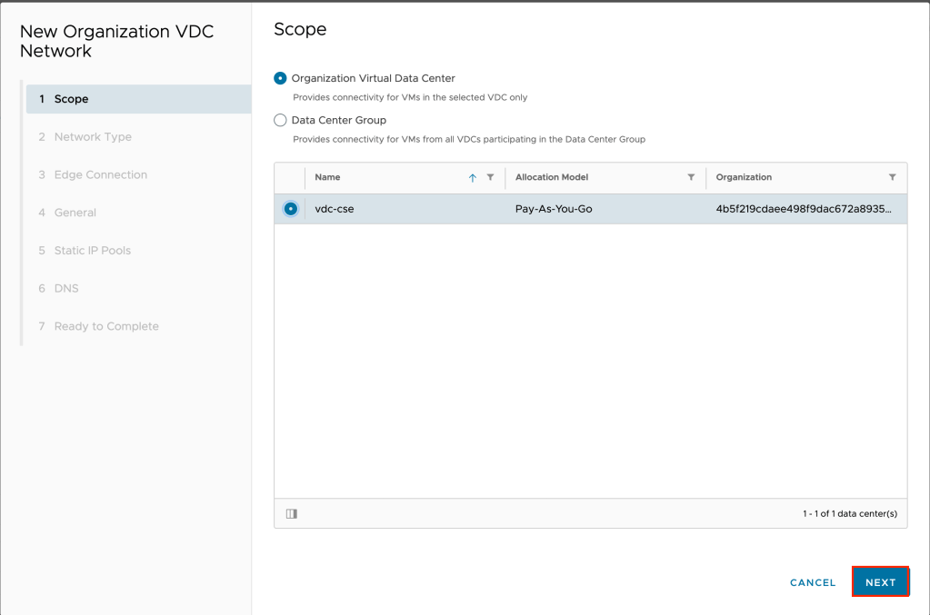
Leave the scope at default (Organization Virtual Data Center) and select your VDC and click NEXT.
For this first network, we will be created the External network so leave the network type as routed and click NEXT.

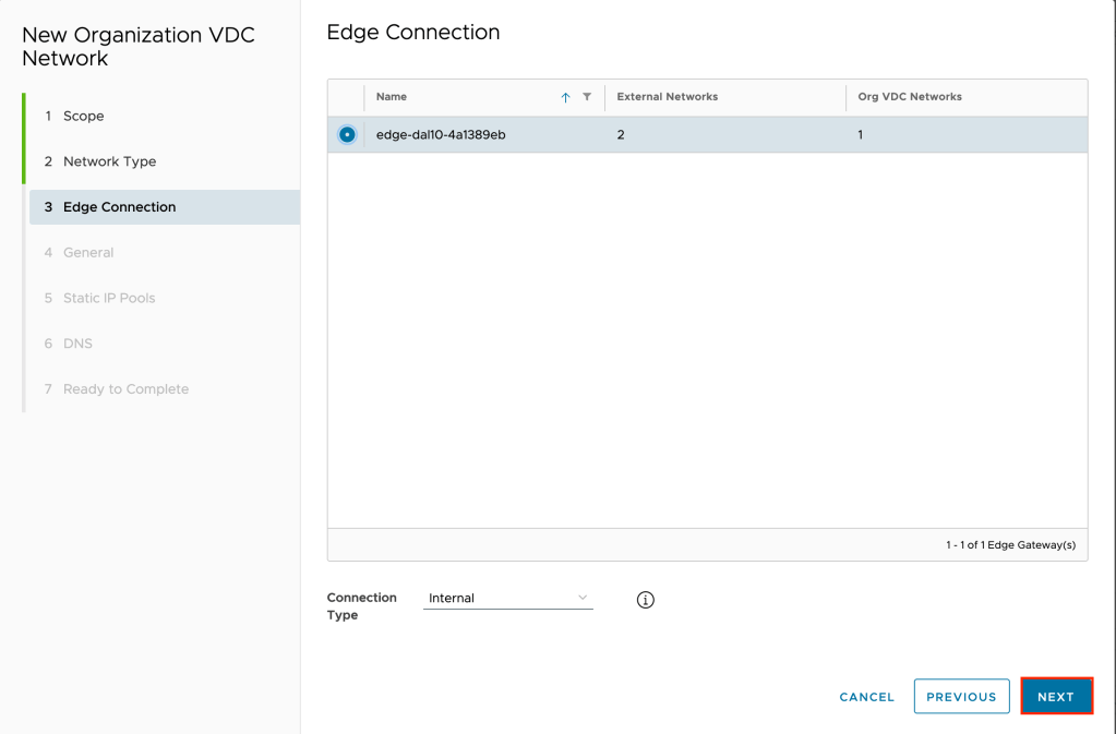
Select your edge connection and leave the connection type as Internal and click NEXT.
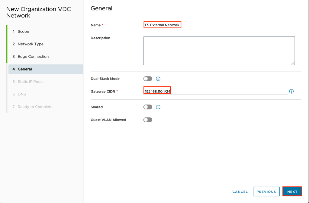
Give the network a name and a CIDR block. In the example F5 External Network is used for the name and 192.168.110.1/24 for the CIDR. Click NEXT to continue.
Create a static IP pool for your network. Since this is the external network of the F5 we only need a single IP address in the pool. In the example 192.168.110.2 is used. Click NEXT to continue once you have added the IP pool.

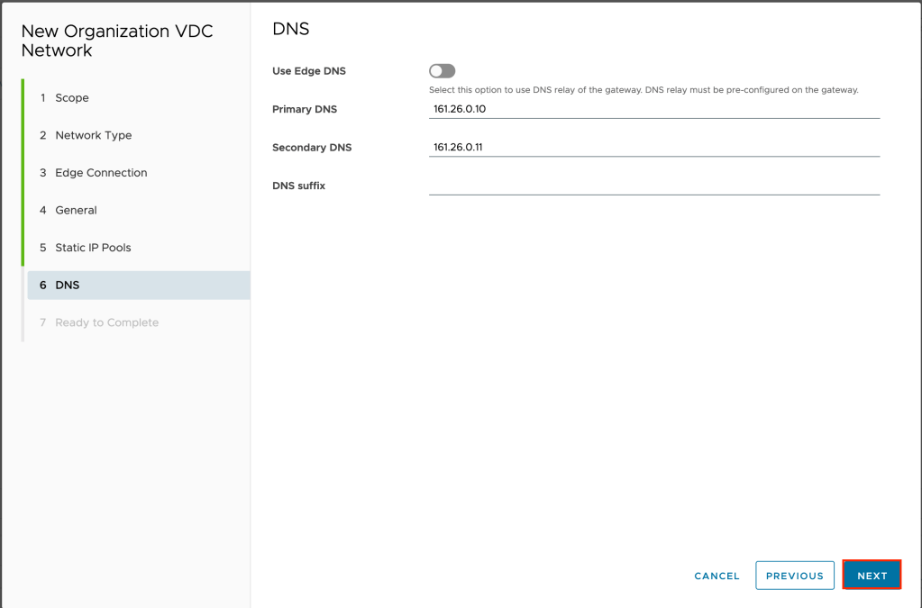
Optionally configure DNS. In the example I am not using the default DNS but using the external DNS servers of IBM Cloud. Click NEXT to continue.
Review your inputs and click FINISH to create the new network.

It will take a few minutes for the network to be created. Once created click on NEW again to start the wizard over for the F5 internal network.
As previously, leave the scope at default (Organization Virtual Data Center) and select your VDC and click NEXT.
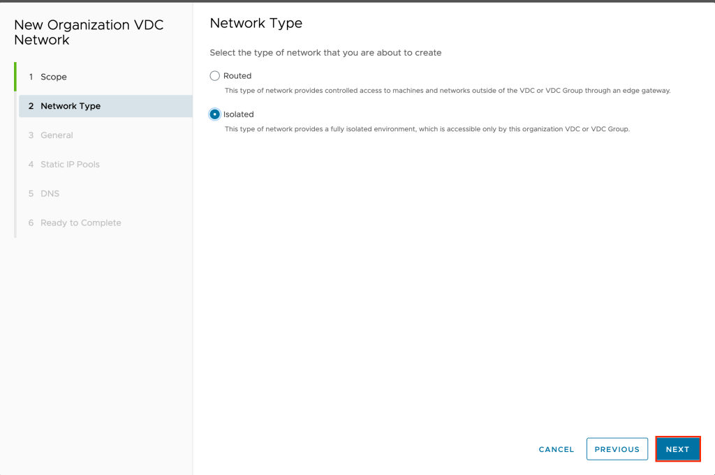
For the network type, this time we are going to choose Isolated as opposed to Routed. The reason for this is that for the internal traffic behind the F5 we do not want it to use the edge gateway inside VMware vCloud Director to provide network access. Instead, the F5 will be providing this access, therefore we set this network to Isolated. Click NEXT to continue.
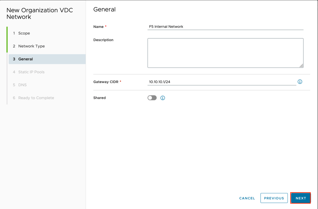
Give the network a name and a CIDR block. In the example F5 Internal Network is used for the name and 10.10.10.1/24 for the CIDR. Click NEXT to continue.
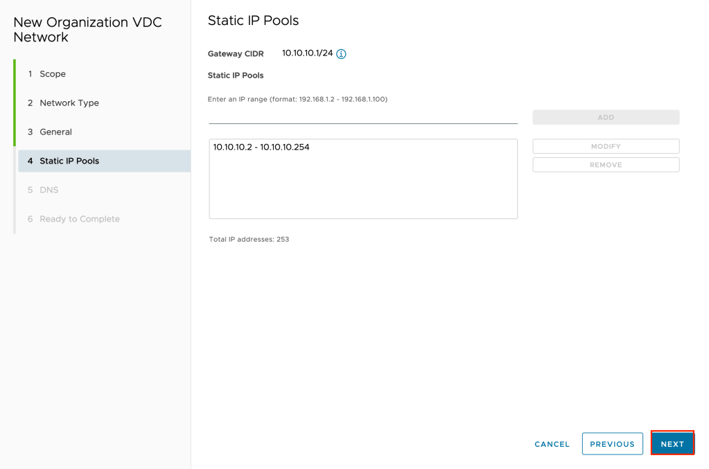
Once again, create a static IP pool. In this example the entire range of the CIDR block is used, so 10.10.10.2-10.10.10.254. Click NEXT to continue.
Optionally configure DNS. In the example I am not using the default DNS but using the external DNS servers of IBM Cloud. Click NEXT to continue.

Review your inputs and click FINISH to create the new network.

Since this network is isolated it should only take a few seconds to complete.
Now that we have created our two new networks we need to attach them to our F5. From the current screen slick on Applications.

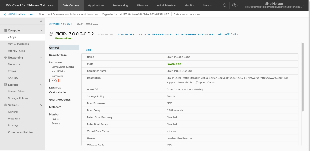
Make sure you are on the virtual machines tab, then click on DETAILS on the virtual BIG-IP virtual machine previously deployed.

Click on the NICs tab.
Click on EDIT to adjust the existing networks.

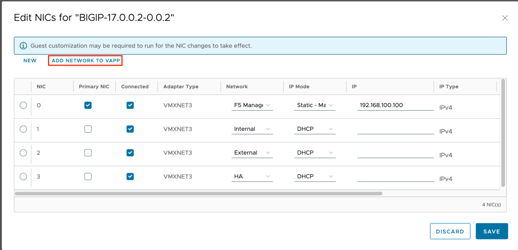
We need to add our two new networks to the vApp. Click on ADD NETWORK TO VAPP.
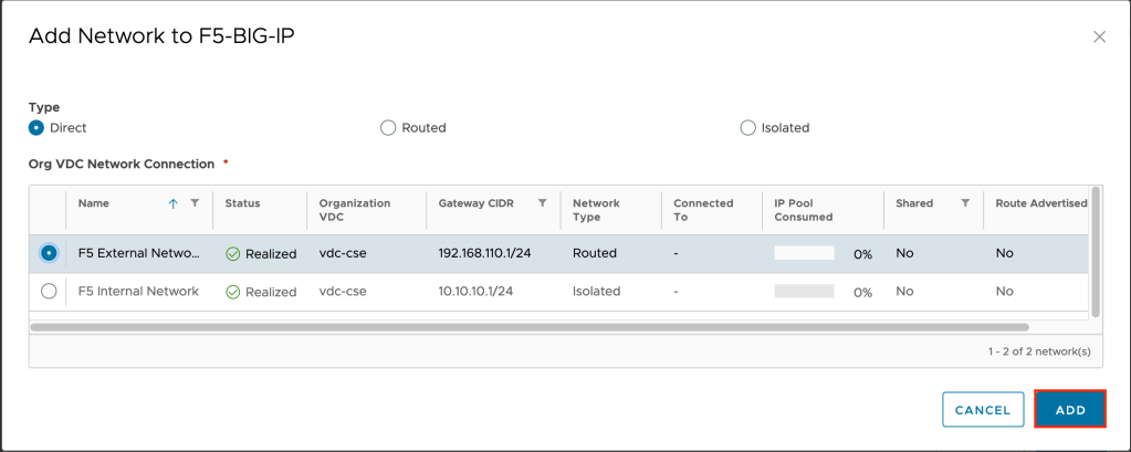
For type select Direct, then select the F5 External Network you created previously and click on ADD.
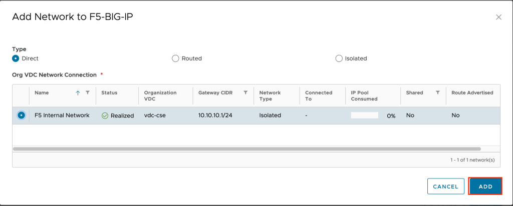
The network will be added, but you won’t see a change in the edit NICs screen. You will see a task run in vCloud Director showing the change. Once that is complete repeat the previous steps, adding the F5 Internal Network to the vApp as well.
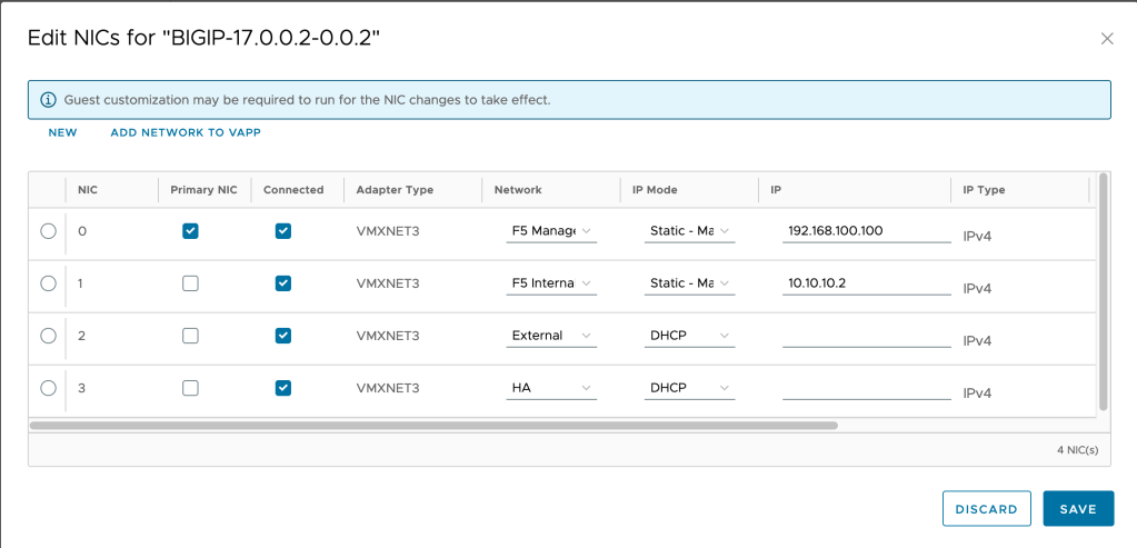
Now that we have added our networks, we can assign them to the appropriate NICs on the virtual machine and assign IP addresses to them. In this case we want to assign the F5 Internal Network to NIC 1 and the F5 External Network to NIC 2.
So for NIC 1, in the Network field use the drop down and select F5 Internal Network. Once selected change the IP Mode to Static-Manual as type in an IP address for the Interface. In the example 10.10.10.2 is used.
Repeat for NIC 2, this time selecting F5 External Network for the network and 192.168.110.2 for the IP address.
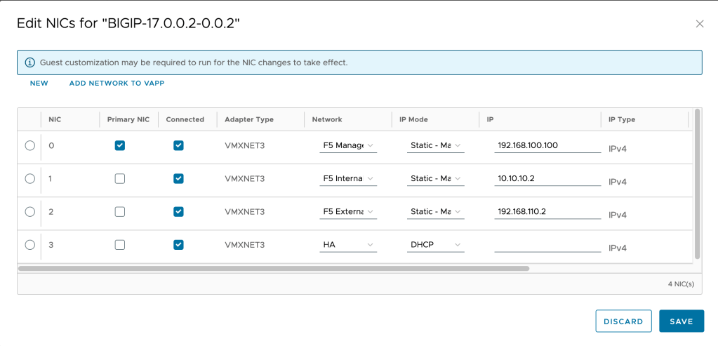
Click SAVE to continue. Your networks should now look similar to the following.

At this point your networks are complete, and ready to be configured in the F5. In the next post I’ll go through configuring the F5 networks.


Leave a comment